Air compressor
Main parts:
1. Separator
2. Pump
3. Motor
4. Air cooler
5. Filter
6. Oil tank
7. Reservoir
8. Air dryer
9. Exhaust fan
1. Separator: Separators separates air and oil. Then the separated air is reserved in reservoir by output line.
2. Pump: Pump is a device which pumps air from motor and oil from oil tank. Oil reduces the friction in screw and increases air pressure. Then air is supplied to the filter.
3. Filter: Filter is a device which purifies the air and reduces unwanted substance from air. The filter air is supplied in the separator.
4. Motor: Motor helps to collect the air from the atmosphere by the help of blower.
5. Air cooler: Air cooler is used to cool the atmospheric air. It places on the motor.
6. Reservoir tank: There are two reservoirs which reserve separated purifies air from oil.
7. Air dryer: Air dryer collects air from reservoir tank and dries the air by the help of compressor. After drying the air, it is supplied for machine use.
8.Exhaust fan: It is used to cool the machine removing heated air.
Description: The electric motor produces air with the help of blower from the atmospheric air. The motor is cooled by air cooler. The air passes through the screw. In the screw oil is supplied from oil tank to reduce friction so that the Screw rotates freely. Then the air and small amount of oil through the pump the pump increases the pressure of air and pass into the filter to reduce the impurities from air. After filtering the air enters into the oil tank. In oil tank, there is a separator which separates the oil and air. Then the air passes through the pipe line and enters into the reservoirs to reserve the air and pass through the dryer. In dryer the air is dried and passes through the pipe to the use of various machines.
Application: To produce dry air.
Gas Generator
Main parts:
a. Electrical part
b. Mechanical part
a. Electrical part:
1. Stator
2. Rotor
3. Spinder
4. Slots
5. Rings
6. Brushes
7. Case bars
8. End rings
9. Cage winding
10. Stator core
11. Stator frame
b. Mechanical parts:
1. Throttle valve
2. Intake manifold
3. Push rod
4. Engine cooling water return line
5. Rocker arm(exhaust)
6. Ignition coil
7. Crank case ventilator
8. Piston
9. Exhaust gas manifold
10. Piston pin
11. Cylinder line
12. Main engine oil ducts
13. Tappets
14. Cam shaft
15. Piston cooling nozzle
16. Crank shaft with counter weight
17. Crank case
18. Engine oil pump
19. Engine oil pan.
Main operation in mechanical parts:
a) Water cooling system:
1. Cooling tower
2. Feed pump
3. Heat exchanger
4. Return water line
5. Jacket water line
1) Cooling tower: The main purpose of cooling tower is to cool the water. In cooling tower a large fan is always rotated by motor to reduce the heat of water.
2) Feed pump: It helps to transmit the water in cooling tower. The feed pump line is connected between cooling tower and heat exchanger.
3) Heat exchanger: It is a device which is used to reduce the temperature of return water.
4) Return water line: After cooling water it passes through the generator body to reduce its heat. Generally the return water temperature is kept in 57-58°C.
5) Jacket water line: The heated water which cooled the engine body it comes out from the body by jacket water line. It is connected with heat exchanger to return the water in cooling tower. Generally the jacket water temperature is 60-70°C.
b) Circulation of fuel:
1. Engine oil supply line
2. Gas mixture cylinder
3. Heat exchanger
4. Engine oil filter
5. Engine oil return line
1) Engine oil supply line: It is connected with oil tank and supply oil into the engine by supply line.
2) Gas mixture cylinder: In gas mixture cylinder, the ratio of air and gas is 11:1. The carburetor mixes the air and gas by help of oil.
3) Heat exchanger: Heat exchanger decreases the temperature of oil.
4) Engine oil filter: It reduces the impurities from oil.
5) Engine oil return line: Filtered oil is gone through the exhaust gas
turbocharge by the engine oil return line. The oil circulates the engine body continuously.
c) Ignition system: Gas engines are are equipped with a microprocessor controlled capacitor discharge ignition system.. The ignition system is run with a supply voltage of 2 ᶲ V DC.
1. Firing sequence
2. Ignition pulse
3. Ignition point
1) Firing sequence: The firing sequence is adjusted by adapting the ignition box.
2) Ignition pulse: The ignition box supplies the ignition energy to the ignition coils, which then generates the high tension voltage for the spark plug.
3) Ignition point: The firing point is optimized by the engine management system depending on operating conditions and type of fuel gas used.

Figure: Cross section parts of gas generator
Function and operation of various parts:
1. Intake air collector: It collects air from the blower which connected by a motor in the body of generator.
2. Gas mixture: In gas mixer cylinder it mixed gas and air.
3. Actuator: Actuator maintains pressure of gas mixer.
4. Engine cooling water pump: Engine cooling water pump cool the water to prevent over heated the engine body.
5. Engine cooling water return line: After surrounding the water in the body the water go through the return line.
6. Temperature control valve: Temperature control valve control the water temperature of the engine body.
7. Ignition coil: Ignition coil help to create firing sequence by DC voltage system.
8. Cylinder: In cylinder the combustion process is done.
9. Cylinder head: Cylinder head is connected with cylinder and the firing of ignition is occurring in the place.
10. Cylinder head cover: Cylinder cover protected the cylinder head and cylinder.
11. Exhaust gas manifold: After combustion the exhaust gas came out by exhaust gas manifold.
12. Starter: It helps to start engine.
13. Engine oil pan: Mainly oil reserve in oil pan which circulated the engine.
14. Toothed flywheel: And by the rotating of flywheel electrical part produce power.
Application:
It produces power which is used to run the mills.
E.T.P
E.T.P: Effluent treatment plant (E.T.P) is one kind of biochemical water treatment plant. E.T.P seeks to manage four main problem areas: scaling, corrosion, microbiological activity and disposal of residual waste. It reduces the toxicity and acidity of used and chemicalized water. Generally the pH of water and the ratio of oxygen and hydrogen are controlled to protect environment in this plant.

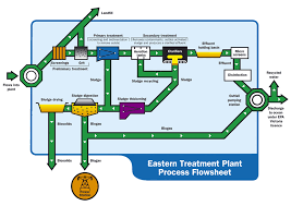
Figure: Process of E.T.P
Major parts of E.T.P
1. Equalization tank: Equalization tank reserves the waste and chemicalized water. In this tank diffuser pipe line is connected to increase the oxygen of chemicalized water.
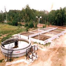
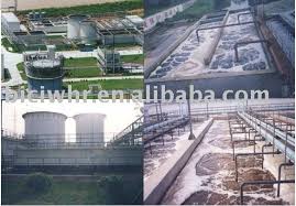
2. Air diffuser: There are four diffusers used to supply air in the tank to increase the amount of oxygen of chemicalized water.
3. Submersible pump: Submersible pump is used to transfer the residual waste water in Flocculation tank from Equalization tank.
4. Flocculation tank: In Flocculation tank, the residual waste water is mixed with FeSO₄, CaO and polyelectrolyte to neutralize the quality of water.

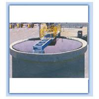
Figure: E.T.P parts
5. Chemical tank: There are five chemical tank to mix the chemical and by feed pump the chemical is supplied to the Flocculation tank.
6. Filter: After neutralized the water is supplied in the filter to separate liquid and other substance.
7. Conditioning tank: After filtering heavy substance of the liquid is collected in conditioning tank.
8. Filter press: In filter press the heavy substance of the liquid is converted in solid form.
9. S.B.R: After filter the liquid substance of water stored in S.B.R-1 and S.B.R-2 tank. In this tank HCl is supplied to control pH. After 4 hours the water is supplied in outlet tank.
10. Outlet tank: By outlet tank the purified water is supplied for other purpose.

Refining process of E.T.P:
The effluent water and waste from the mills enter into the equalization tank. In equalization tank, there are many blowers to supply air for increasing the amount of oxygen of the tank effluent water. From equalization tank the water is pumped into the flocculation tank, there is a flow meter to measure the pumped water. The chemical mixture from the chemical tank and acid from the acid drum pass through pipe and enter the flocculation tank. In the flocculation tank, there are two pipe lines to pass the water. One pipe line is to pass into the conditioning tank and other is filter tank. In filter tank, the water is filtered. After filtering the water enters into the S.B.R -1 and S.B.R-2 tank. In S.B.R-1 1 and S.B.R-2 tank the water stays for four hours. In this tank, pH of water is maintained between 7 to 7.5 In conditioning tank, the mud water is pumped through the water tank and filter tank. In filter tank, the water is filtered by the filter machine and the filtering water gain enters into theconditioning tank.
Application:
The toxic waste water is harmful for the environment. SO the E.T.P process is applied to reduce the toxicity of the waste water and protect the environment.
Singing and Desizing Machine
Singeing: Singeing is a process to burn off the surface fibers from the fabric to produce smoothness. The fabric passes over brushes to raise the fibers, and then passes over a plate heated by gas flames.
Desizing: Desizing is a process to remove sizing chemical and other impurities.
Parts of machine:
1. Burner chamber
2. Chemical reaction chamber


Figure: Singing and Desizing Machine
Scouring Bleaching machine
Scouring: Scouring is the process to reduce the residue of cloth by using high strength NaOH.
Bleaching: Bleaching is the process to improve whiteness by removing natural coloration and remaining trace impurities from the cotton.
Section of machine:
1. Scouring
2. Bleaching
3. Drying


Figure: Scouring Bleaching machine
Air compressor: Air compressor is a machine which produces dry air from atmosphere. It is necessary to run various types of machine.
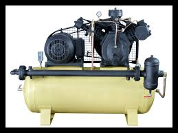
Figure: Air compressor
Figure: Air compressor
Main parts:
1. Separator
2. Pump
3. Motor
4. Air cooler
6. Oil tank
7. Reservoir
8. Air dryer
9. Exhaust fan
1. Separator: Separators separates air and oil. Then the separated air is reserved in reservoir by output line.
2. Pump: Pump is a device which pumps air from motor and oil from oil tank. Oil reduces the friction in screw and increases air pressure. Then air is supplied to the filter.
3. Filter: Filter is a device which purifies the air and reduces unwanted substance from air. The filter air is supplied in the separator.
4. Motor: Motor helps to collect the air from the atmosphere by the help of blower.
5. Air cooler: Air cooler is used to cool the atmospheric air. It places on the motor.
6. Reservoir tank: There are two reservoirs which reserve separated purifies air from oil.
7. Air dryer: Air dryer collects air from reservoir tank and dries the air by the help of compressor. After drying the air, it is supplied for machine use.
8.Exhaust fan: It is used to cool the machine removing heated air.
Description: The electric motor produces air with the help of blower from the atmospheric air. The motor is cooled by air cooler. The air passes through the screw. In the screw oil is supplied from oil tank to reduce friction so that the Screw rotates freely. Then the air and small amount of oil through the pump the pump increases the pressure of air and pass into the filter to reduce the impurities from air. After filtering the air enters into the oil tank. In oil tank, there is a separator which separates the oil and air. Then the air passes through the pipe line and enters into the reservoirs to reserve the air and pass through the dryer. In dryer the air is dried and passes through the pipe to the use of various machines.
Application: To produce dry air.
Gas Generator
Gas Generator: Generator is a device that converts mechanical energy to electrical energy. The source of mechanical energy may be reciprocating, water filling through a water wheel. The reverse conversation of electrical into mechanical energy is done by electric motor.
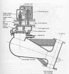
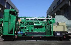
Figure: Gas generator
Figure: Gas generator
Main parts:
a. Electrical part
b. Mechanical part
a. Electrical part:
1. Stator
2. Rotor
3. Spinder
4. Slots
5. Rings
6. Brushes
7. Case bars
8. End rings
9. Cage winding
10. Stator core
11. Stator frame
b. Mechanical parts:
1. Throttle valve
2. Intake manifold
3. Push rod
4. Engine cooling water return line
5. Rocker arm(exhaust)
6. Ignition coil
7. Crank case ventilator
8. Piston
9. Exhaust gas manifold
10. Piston pin
11. Cylinder line
12. Main engine oil ducts
13. Tappets
14. Cam shaft
15. Piston cooling nozzle
16. Crank shaft with counter weight
17. Crank case
18. Engine oil pump
19. Engine oil pan.
Main operation in mechanical parts:
a) Water cooling system:
1. Cooling tower
2. Feed pump
3. Heat exchanger
4. Return water line
5. Jacket water line
1) Cooling tower: The main purpose of cooling tower is to cool the water. In cooling tower a large fan is always rotated by motor to reduce the heat of water.
2) Feed pump: It helps to transmit the water in cooling tower. The feed pump line is connected between cooling tower and heat exchanger.
3) Heat exchanger: It is a device which is used to reduce the temperature of return water.
4) Return water line: After cooling water it passes through the generator body to reduce its heat. Generally the return water temperature is kept in 57-58°C.
5) Jacket water line: The heated water which cooled the engine body it comes out from the body by jacket water line. It is connected with heat exchanger to return the water in cooling tower. Generally the jacket water temperature is 60-70°C.
b) Circulation of fuel:
1. Engine oil supply line
2. Gas mixture cylinder
3. Heat exchanger
4. Engine oil filter
5. Engine oil return line
1) Engine oil supply line: It is connected with oil tank and supply oil into the engine by supply line.
2) Gas mixture cylinder: In gas mixture cylinder, the ratio of air and gas is 11:1. The carburetor mixes the air and gas by help of oil.
3) Heat exchanger: Heat exchanger decreases the temperature of oil.
4) Engine oil filter: It reduces the impurities from oil.
5) Engine oil return line: Filtered oil is gone through the exhaust gas
turbocharge by the engine oil return line. The oil circulates the engine body continuously.
c) Ignition system: Gas engines are are equipped with a microprocessor controlled capacitor discharge ignition system.. The ignition system is run with a supply voltage of 2 ᶲ V DC.
1. Firing sequence
2. Ignition pulse
3. Ignition point
1) Firing sequence: The firing sequence is adjusted by adapting the ignition box.
2) Ignition pulse: The ignition box supplies the ignition energy to the ignition coils, which then generates the high tension voltage for the spark plug.
3) Ignition point: The firing point is optimized by the engine management system depending on operating conditions and type of fuel gas used.
Figure: Cross section parts of gas generator
Function and operation of various parts:
1. Intake air collector: It collects air from the blower which connected by a motor in the body of generator.
2. Gas mixture: In gas mixer cylinder it mixed gas and air.
3. Actuator: Actuator maintains pressure of gas mixer.
4. Engine cooling water pump: Engine cooling water pump cool the water to prevent over heated the engine body.
5. Engine cooling water return line: After surrounding the water in the body the water go through the return line.
6. Temperature control valve: Temperature control valve control the water temperature of the engine body.
7. Ignition coil: Ignition coil help to create firing sequence by DC voltage system.
8. Cylinder: In cylinder the combustion process is done.
9. Cylinder head: Cylinder head is connected with cylinder and the firing of ignition is occurring in the place.
10. Cylinder head cover: Cylinder cover protected the cylinder head and cylinder.
11. Exhaust gas manifold: After combustion the exhaust gas came out by exhaust gas manifold.
12. Starter: It helps to start engine.
13. Engine oil pan: Mainly oil reserve in oil pan which circulated the engine.
14. Toothed flywheel: And by the rotating of flywheel electrical part produce power.
Application:
It produces power which is used to run the mills.
E.T.P
E.T.P: Effluent treatment plant (E.T.P) is one kind of biochemical water treatment plant. E.T.P seeks to manage four main problem areas: scaling, corrosion, microbiological activity and disposal of residual waste. It reduces the toxicity and acidity of used and chemicalized water. Generally the pH of water and the ratio of oxygen and hydrogen are controlled to protect environment in this plant.
Figure: Process of E.T.P
Major parts of E.T.P
1. Equalization tank: Equalization tank reserves the waste and chemicalized water. In this tank diffuser pipe line is connected to increase the oxygen of chemicalized water.
2. Air diffuser: There are four diffusers used to supply air in the tank to increase the amount of oxygen of chemicalized water.
3. Submersible pump: Submersible pump is used to transfer the residual waste water in Flocculation tank from Equalization tank.
4. Flocculation tank: In Flocculation tank, the residual waste water is mixed with FeSO₄, CaO and polyelectrolyte to neutralize the quality of water.
Figure: E.T.P parts
5. Chemical tank: There are five chemical tank to mix the chemical and by feed pump the chemical is supplied to the Flocculation tank.
6. Filter: After neutralized the water is supplied in the filter to separate liquid and other substance.
7. Conditioning tank: After filtering heavy substance of the liquid is collected in conditioning tank.
8. Filter press: In filter press the heavy substance of the liquid is converted in solid form.
9. S.B.R: After filter the liquid substance of water stored in S.B.R-1 and S.B.R-2 tank. In this tank HCl is supplied to control pH. After 4 hours the water is supplied in outlet tank.
10. Outlet tank: By outlet tank the purified water is supplied for other purpose.
Refining process of E.T.P:
The effluent water and waste from the mills enter into the equalization tank. In equalization tank, there are many blowers to supply air for increasing the amount of oxygen of the tank effluent water. From equalization tank the water is pumped into the flocculation tank, there is a flow meter to measure the pumped water. The chemical mixture from the chemical tank and acid from the acid drum pass through pipe and enter the flocculation tank. In the flocculation tank, there are two pipe lines to pass the water. One pipe line is to pass into the conditioning tank and other is filter tank. In filter tank, the water is filtered. After filtering the water enters into the S.B.R -1 and S.B.R-2 tank. In S.B.R-1 1 and S.B.R-2 tank the water stays for four hours. In this tank, pH of water is maintained between 7 to 7.5 In conditioning tank, the mud water is pumped through the water tank and filter tank. In filter tank, the water is filtered by the filter machine and the filtering water gain enters into theconditioning tank.
Application:
The toxic waste water is harmful for the environment. SO the E.T.P process is applied to reduce the toxicity of the waste water and protect the environment.
Singing and Desizing Machine
Singeing: Singeing is a process to burn off the surface fibers from the fabric to produce smoothness. The fabric passes over brushes to raise the fibers, and then passes over a plate heated by gas flames.
Desizing: Desizing is a process to remove sizing chemical and other impurities.
Parts of machine:
1. Burner chamber
2. Chemical reaction chamber
Figure: Singing and Desizing Machine
Scouring Bleaching machine
Scouring: Scouring is the process to reduce the residue of cloth by using high strength NaOH.
Bleaching: Bleaching is the process to improve whiteness by removing natural coloration and remaining trace impurities from the cotton.
Section of machine:
1. Scouring
2. Bleaching
3. Drying
Figure: Scouring Bleaching machine
great article.that promtes best practicesa.....
ReplyDelete:Air Compressor Pipes